Led Flasher Circuit Diagram With 555
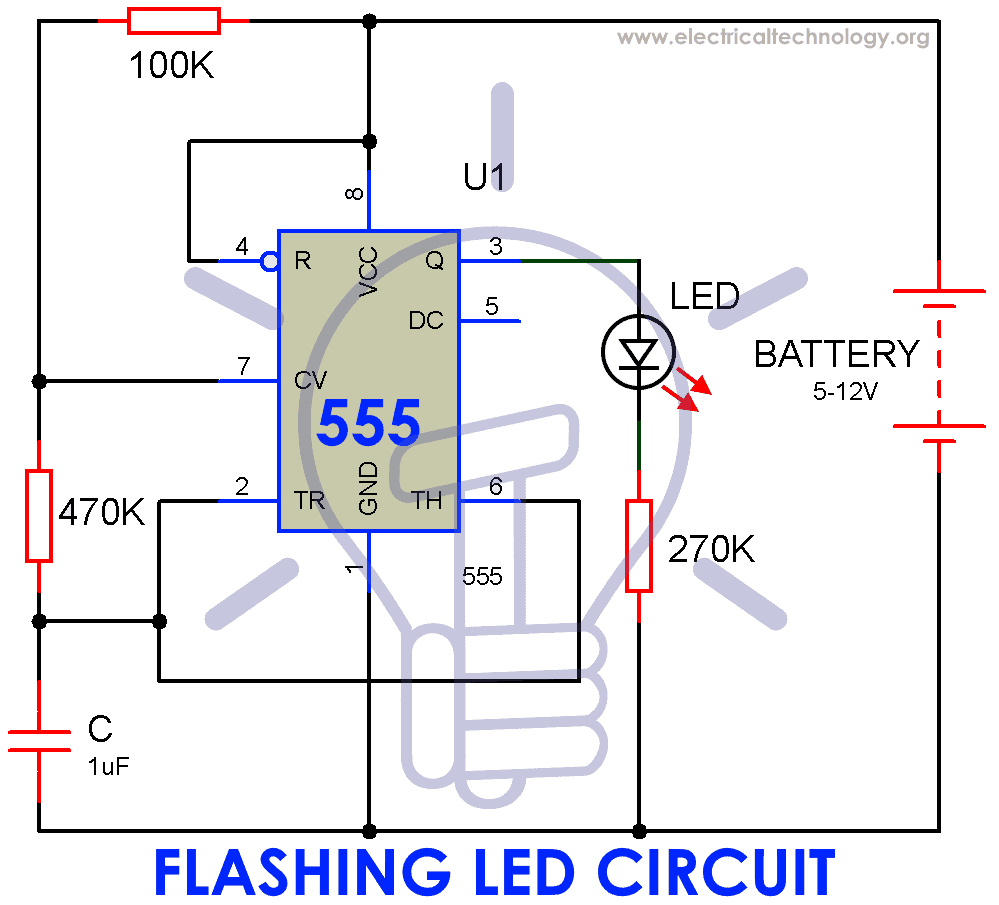
Circuit Diagram: Here is a circuit diagram of Automatic LED Blinking Circuit using 555 Timer IC. Assemble the circuit in breadboard and connect the power supply, LED will automatic starts blinking. 555 Timer IC: 555 timer IC is the cheap, popular and precise timing device used in various applications.

Automatic LED Blinking Circuit using 555 Timer IC LED Flasher
538 sq ft. Canal view. Sleeps 2. 1 Queen Bed. Stay at this guesthouse in Venice. Enjoy free WiFi, a TV, and premium bedding. Popular attractions Piazzale Roma and St. Mark's Square are located nearby. Discover genuine guest reviews for Grand Canal Suites, in Santa Croce neighborhood, along with the latest prices and availability - book now.
Led flasher circuit 555 timer history, flashlight iphone 3gs best themes
Created on: 31 July 2012 A 555 (triple five) timer IC (integrated circuit) is used in this tutorial to flash an LED on and off. The circuit is easy to build on an electronic breadboard for beginners. The video below shows the circuit in action: Video unavailable This video is unavailable Watch on Can't see the video? View on YouTube →

LED flasher circuit using 555 IC simple electronics
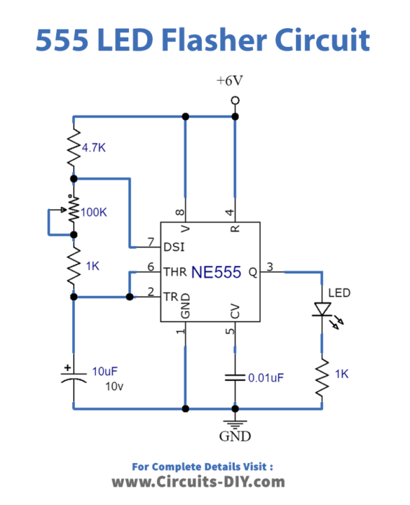
In this tutorial, I will show you how to design and build a simple 555 LED Flasher Circuit. I implemented this LED Flasher circuit in such a way that it mimics a Police Flasher instead of a simple ON-OFF sequence. Outline Introduction 555 Timer IC is one fascinating integrated circuit.
on off timer circuit diagram
LED Flasher Circuit using 555 Timer August 28, 2019 by Anas Ejaz 15,718 views Contents hide 1 Hardware Components 2 555 IC Pinout 3 Circuit Diagram 4 Connection 5 Working Explanation 6 Application In this tutorial, we will show you how to make an LED flasher or LED blinking circuit using the 555 Timer IC.
Simple 555 LED Flasher
In this video, we are going to show you making an LED flasher circuit at home easily. To make this circuit we use NE555N Timer chip and a few electronics com.

Adjustable Flashing/Blinking LED circuit on Breadboard 555 Timer Project 5 YouTube
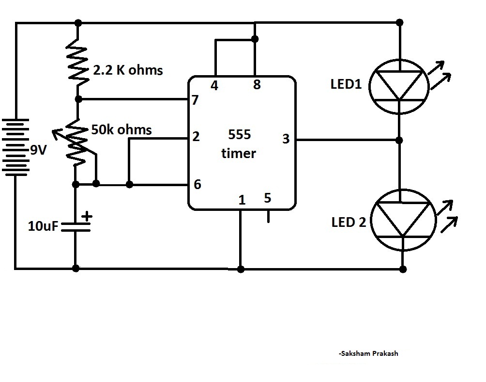
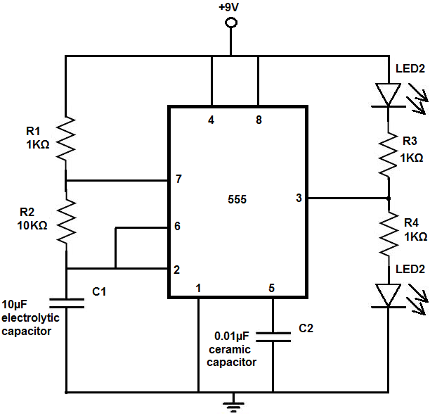
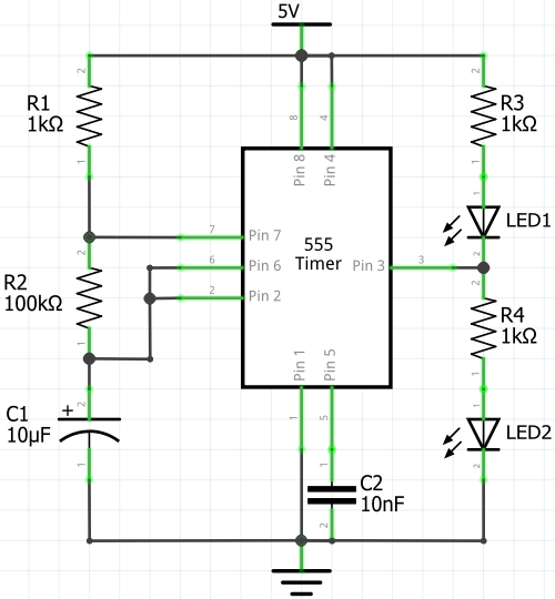
Alternating LED Flasher With 555 IC Circuit Diagram. This alternate LED flasher consists of a pair of LEDs that blink alternately. It has the same circuit as a simple LED flasher circuit using a 555 astable multivibrator. The only difference is that one more LED is added in the circuit, which ON when the 555 output is in a low state.
555 led flasher wiring diagram
This circuit toggles an LED or any output device ON and OFF at regular intervals of time. The duration between successive toggling of LED can be adjusted by using a potentiometer. Watch the video above for detailed step by step instructions on how to build this circuit. Explanation of how the circuit works is also included in the video.

555 Timer Basics Astable Mode
A tutorial on how to make a flashing / Blinking / Pulsing LED lights circuit using IC 555 Timer on a Breadboard. In this project the NE555 IC works in astabl.

10+ Flashing Led Circuit Using 555 Timer Robhosking Diagram
Steps to Make a Simple LED Flashing Circuit. Collect all the required components and get ready to put all the components together! Step 1:- Put the 555 timer IC on breadboard. Step 2:- Connect pin 1 of 555 Timer IC to the ground as shown below. You can see the pin structure of 555 Timer IC in the pin diagram shown above.

Led Blinking Using 555 Timer
A 555 LED flasher circuit for beginners in electronics. In this tutorial, a 555 (triple five) timer IC (integrated circuit) is used to flash or blink an LED on and off. The circuit is easy to build on an electronic breadboard for beginners. The video below shows the 555 LED flasher circuit in action: In this tutorial you will learn:

How to make LED flasher with 555 Timer eediary
A Tutorial on how to make a Flashing/Blinking LED circuit using 555 Timer IC on a breadboard. This circuit flashes LED lights at regular intervals of time an.

A Simple Flasher Light Circuit Diagram (Using IC 555) ETechnoG
Step 1: What You Need What You Need To Build The Circuit- 1x 555 timer ic, 1x 33uf, (or any capacitor the higher uf the lower the blink rate!) 1x 10k Resistor, 1x 1k Resistor, 1x 270 ohm resistor, 1x LED, 1x 9 volt battery clip, 1x 9 volt battery, 3x Breadboard jumper wires, 1x Breadboard.
555 Blinker Circuit Multisim Live
50+ LED Light Projects & Circuits led flashers Share this: Share More This is a small size led flasher built with the 555 timer IC that is powered from 2 x 1.5V batteries. The circuit can be used as a flashing metronome, dark room timer, memo-reminder or other similar applications. Schematics of LED Flasher with the 555 timer IC 555 datasheet
Dual LED Flasher Using 555 Timer Lindevs
Step 1: Take All Parts As Given in the List Components required - (1.) Timer IC - 555 x1 (2.) Resistor - 1K & 10K x1 (3.) Power supply - 5V DC (4.) Capacitor - 16V 100uf (5.) LED - 3V x2 Ask Question Step 2: Connect All Components - Connect all components on 555 timer IC as shown in picture. NOTE: we can connect all 8-LEDs if you want then connect.

LED Flasher Circuit Diagram with 555 Timer » 555 timer IC
A 555-timer IC is a versatile integrated circuit that can be used in a wide range of electronic applications, including LED flashing circuits. In this tutorial, we will guide you through the process of building a simple LED flashing circuit using a 555-timer IC.